
LUXBEAM® LLS03
Fine RDL at 3 µm
The advanced-packaging workhorse: 3 µm line and space from a 405 / 375 nm laser, at 102 wafers an hour — redistribution layers, IC substrate and fan-out panel RDL on wafers and panels to 510 × 515 mm.
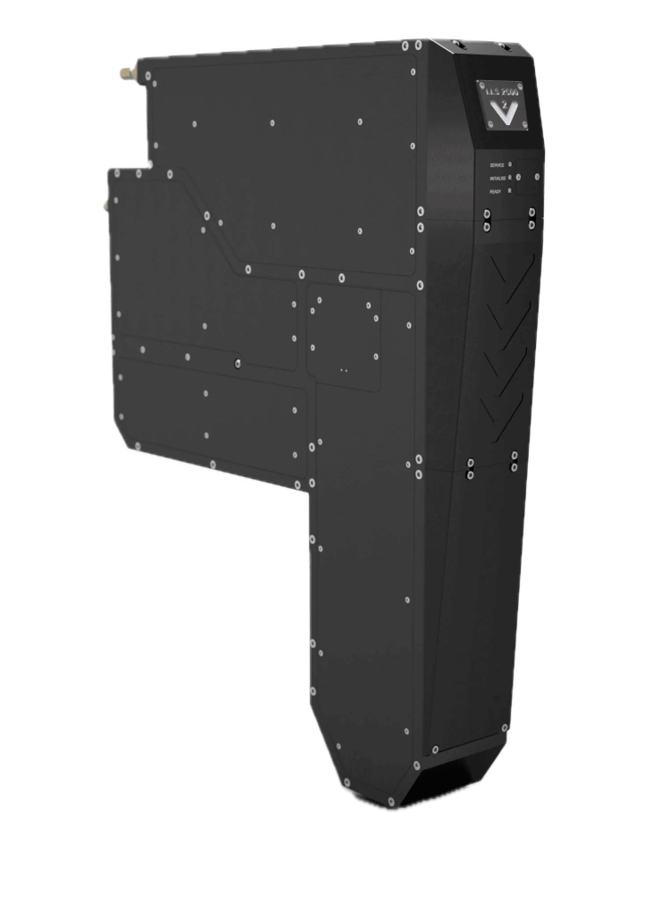
What sets it apart
LLS03 — in three numbers
-
3 µm line and space
Above 90% CD uniformity across wafers and 310 × 310 and 510 × 515 mm panels, with a standard alignment camera.
-
405 / 375 nm laser
Two wavelengths from one head — the shorter for the finest geometry and i-line resists.
-
102 wafers an hour
Or 32 panels an hour on 515 × 510 mm. Three times the LLS02’s throughput, one micrometre coarser.
Application fit
Where LLS03 fits
RDL and interposers
The density step most advanced-packaging lines actually run, on wafer and on panel.
IC substrate
Build-up layers where line width and registration are both budgeted.
CPO and FOPLP fine RDL
Co-packaged optics, and fan-out panel-level packaging at its finest routing layer.
Print testing — on wafer
Patterned by LLS03, actually imaged
Real microscopy of resist patterned by an LLS03. Open a tile to see the full frame.
LLS03 · Optical 3.0 µm
Specifications
LLS03 — at a glance
Imaging & Layout
- Resolution
- 3 µm
- Light source
- 405 / 375 nm laser
- Throughput — Ø300 mm wafer
- 102 wph
- Throughput — 515 × 510 mm panel
- 32 pph
- Typical applications
- RDL and interposers, IC substrate, CPO, FOPLP fine RDL
- Substrate / panel
- Wafers, 310×310, 510×515
- Segment
- Advanced packaging
Integration
- Cooling
- Liquid
- Pattern formats
- GDSII · OASIS · ODB++ · Gerber
- Real-time features
- Positioning · scaling · rotation · warping · re-routing · autofocus
Figures are for discussion and to be confirmed per application. Throughput depends on resist and energy density — send us both and a field application engineer will verify them for your process.
Why Visitech
We engineer the imaging heart
inside your next machine
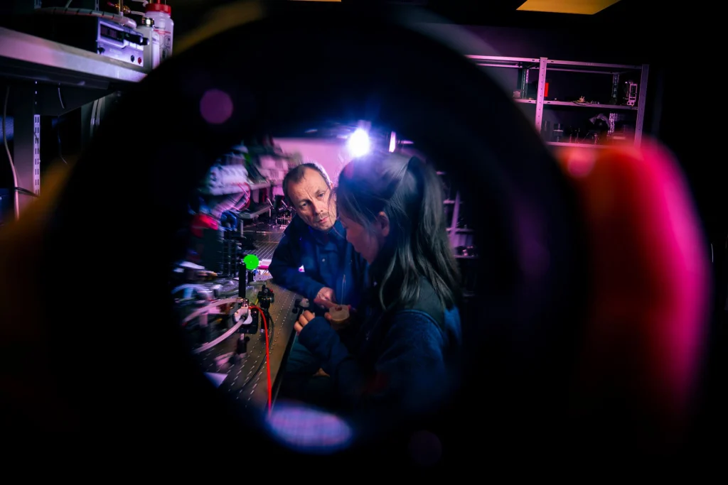
Masks are the past
Maskless DLP-based exposure means zero physical masks to procure, store or replace. Change the design at 2 PM, run production at 3 PM.
Vertically integrated
Every critical element under one roof — tighter tolerances, faster iteration and complete system optimisation that bolt-together solutions cannot match.
Field-proven partner
The industry standard for high-throughput Direct Imaging — running 24/7 in PCB, advanced packaging and semicon production worldwide.

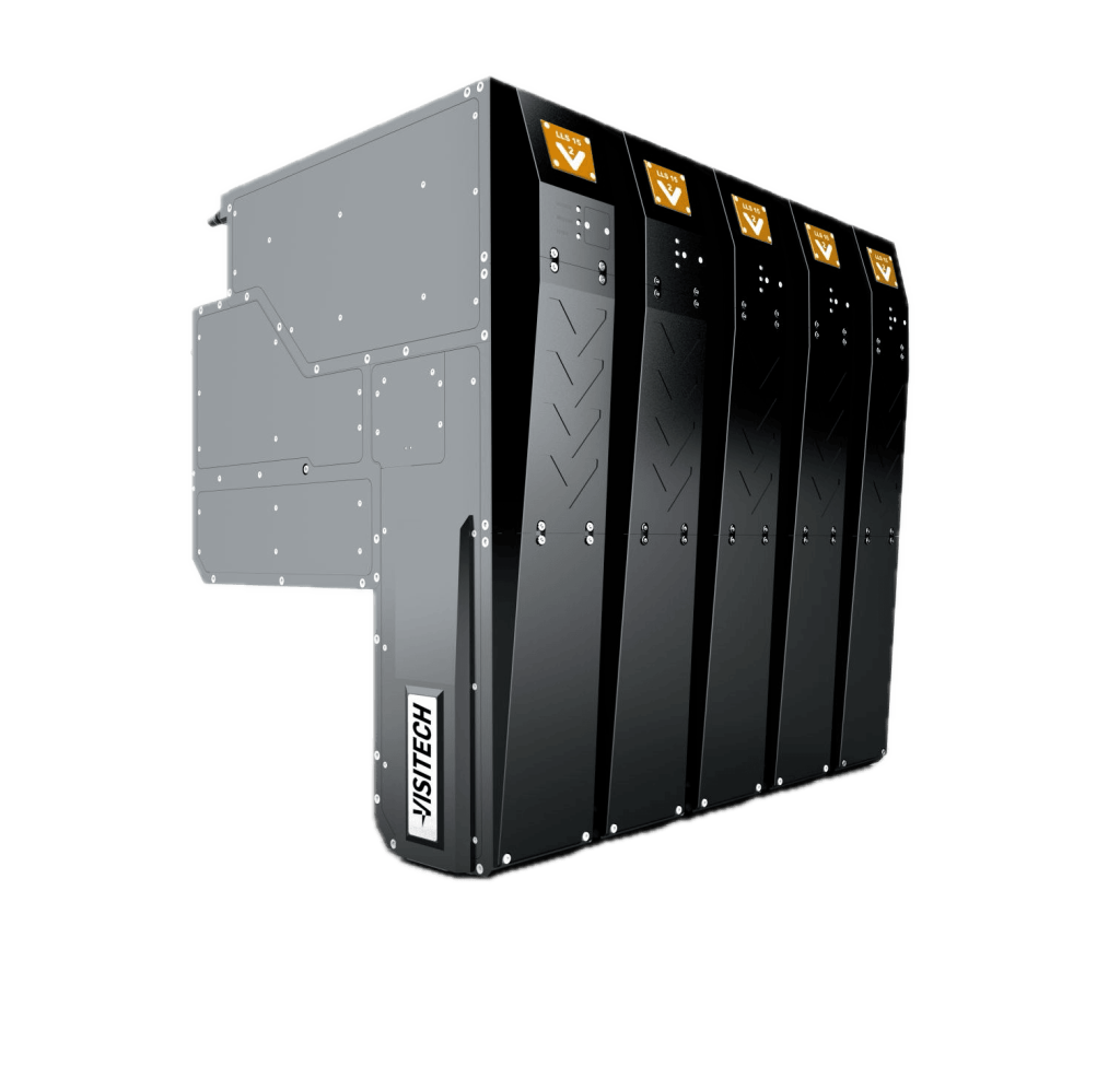
Engineered in-house.
Deployed and supported worldwide.
- Years of DLP experience
- 25+
- Systems deployed
- 15 000+
- Field-proven reliability
- 24/7
Where does the LLS03 sit in the lineup
At 3 µm line and space, between the LLS02 at 2 µm and the LLS05 at 5 µm. It is the head most advanced-packaging lines choose when the finest layer is 3 µm and throughput still has to pay for the tool.
What throughput does it hold
Around 102 wafers an hour on Ø300 mm, or 32 panels an hour on 515 × 510 mm, single pass. Figures are for discussion and confirmed per resist and energy density.
Which formats does it pattern
Wafers, and panels at 310 × 310 and 510 × 515 mm.
Does it come with alignment
Yes — a standard alignment camera, and real-time die-shift compensation through LURIA. A production panel shifts, rotates and warps as it is processed; LURIA patterns around that rather than assuming it away.
Can a process proven on the LLS03 move to another head
Yes. Every LLS photohead runs the same LURIA platform, so a recipe carries across the range — which is the reason to choose within the lineup rather than between vendors.
Not sure which head?
Tell us your line, panel and volume
Send the resist, the target line / space and the format, and a field application engineer comes back with a recommended photohead and a configuration to design around — usually within two business days.
- NorwayHQ · Drammen
- ChinaShanghai
- United StatesAllen, TX
- JapanTokyo